Ultrafast 3D Printing a Design Guide for LSPc Printing
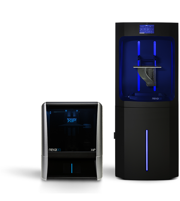
XiP and NXE Series 3D Printers
Table of Contents
Technology Background Our 3D Printers Post-Processing Design Guidelines for LSPc 3D Printing File and Print Preparation Quick Reference Guide
LSPc® technology
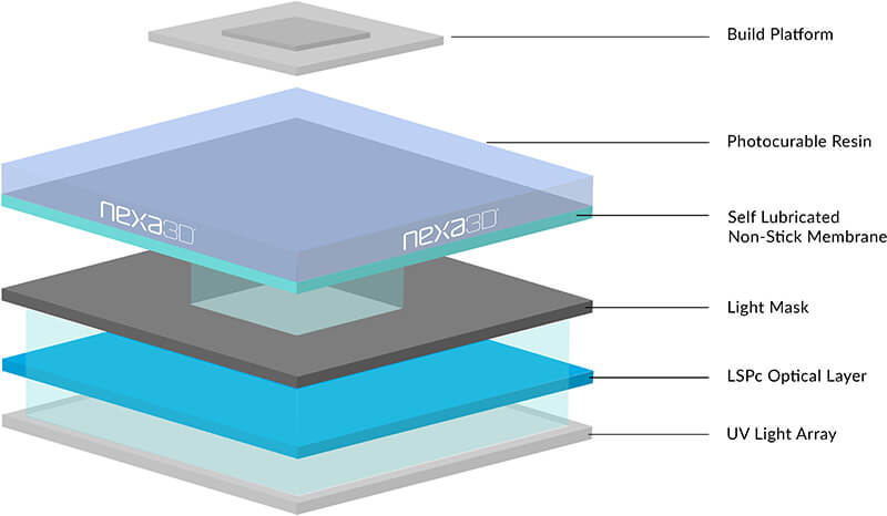
The Nexa3D process
Nexa3D’s proprietary LSPc technology converts photopolymer liquid resin to structural plastic using ultraviolet (UV) light. Advanced membrane technology combined with scalable 4K LCD image masking provide users with a highly productive manufacturing system, allowing users to rapidly iterate on product concepts, then transition immediately to production.
Intelligent NexaX software optimizes every layer for fastest print time with consistent quality. Parts printed on XiP and NXE-series 3D printers exhibit excellent surface finish, full density, and isotropic properties unequaled by other additive manufacturing platforms.
Industries across the globe are enhanced by Nexa3D technology, including customized consumer goods, dentistry, factory tooling, orthopedics, automotive, scientific research, electronics, recreation, entertainment and others. Domain experts exploit the known benefits of additive manufacturing together with the functional materials and productivity of the NXE 400 platform to develop industry-revolutionizing products.
Ultrafast from Nexa3D
3D printing from the desktop to the production floor in record time
 Explore XiP Explore XiP |
 Explore NXE 200 Explore NXE 200 |
 Explore NXE 400 Explore NXE 400 |
|
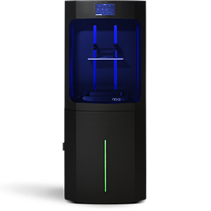
XiP |
NXE 200 |
NXE 400 |
|
Build Volume |
4.8L 195 x 115 x 210mm (7.7 x 4.5 x 8.3 in) |
8.5L 275 x 155 x 200mm (10.8 x 6.1 x 15.7 in) |
16L 275 x 155 x 400mm (10.8 x 6.1 x 15.7 in) |
Technology |
LSPc | LSPc | LSPc |
Pixel Size |
52 µm (0.0020 in) | 76.5 μm (0.0030 in) | 76.5 μm (0.0030 in) |
Max Resolution |
4K (3840 x 2160) | 4K (3840 x 2160) | 4K (3840 x 2160) |
27 Part Print Time* |
43 min | 29 min | 29 min |
Printer Footprint (xyz) |
420 x 350 x 530mm (16.5 x 14 x 21 in) | 710 x 710 x 1675mm (28 x 28 x 66 in) | 710 x 710 x 1675mm (28 x 28 x 66 in) |
Material Packaging |
1kg aluminum cartridge | 5kg jerry can | 5kg jerry can |
*Calculated for 3-way connector file using 200 micron layer height and x45 prototyping material.
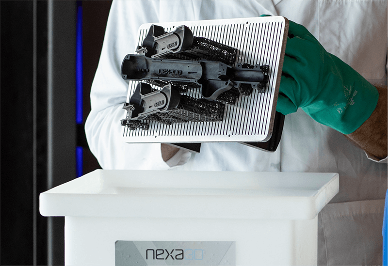
Post-processing
Automated washing and curing for XiP and NXE-Series 3D Printers
Our post-processing 3D printing solutions ensure consistent mechanical properties and predictable part performance for manufacturing with commercial 3D printers.
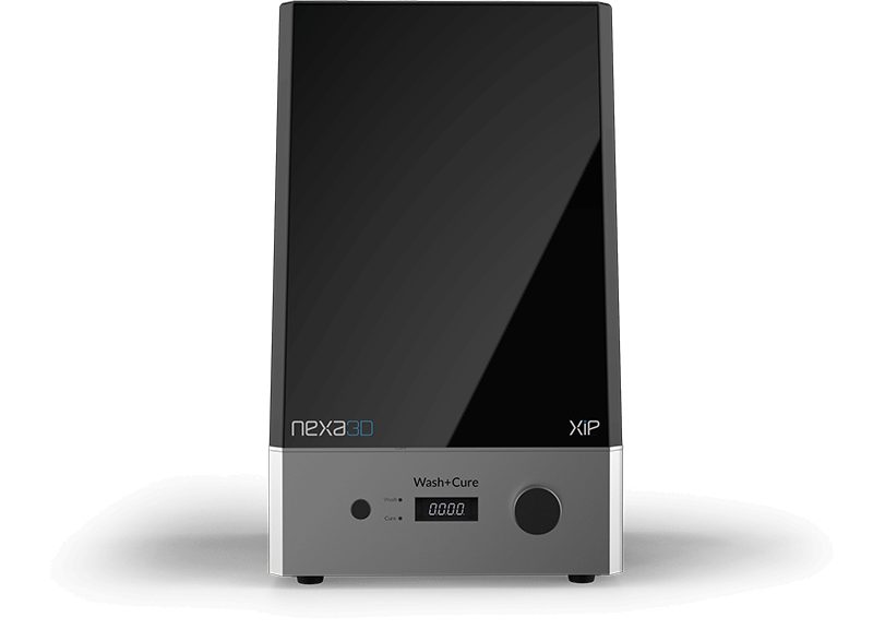
XiP
The XiP Wash + Cure is a 2-in-1 post processing station that provides optimal automated post-processing in a compact package. Simply drop parts into the wash bin with IPA or xCLEAN and run the wash cycle. Then remove the wash bin and place your part on the turntable, fold down the LED arm, and place the reflective cover over the top for post-curing.
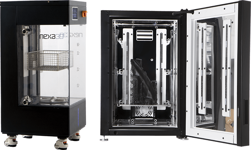
NXE-Series
Nexa3D’s xWASH and xCURE is a powerful one-two punch of washing and curing in large volumes. xWASH allows for the loading of a full build plate and use of IPA or Nexa3D xCLEAN. xCURE can cure multiple build plates simultaneously for maximum dimensional accuracy, structural integrity, and stronger molecularstructures.
General Considerations
Thermal
When designing for the LSPc process, consider the full process workflow and physical constraints. Many of our design guidelines are similar injection molding, since the resin undergoes a phase transformation and shrinkage of 1-2% akin to a thermoplastic solidifying in a mold. However, the shrink is layer by layer, so abrupt changes in exposed cross sections can cause distortions. We’ll provide guidance on how to avoid this issue.
Curing thick sections also results in increasing exothermic heat and some overcuring in the XY plane. NexaX 2.0 software optimizes the print speed to help control temperature. Adding flow allowance for liquid resin further helps avoid thermal gradients in the part as it builds and allows for faster speeds.
Build preparation
The first few layers of your build will be intentionally over-cured to ensure adhesion to the build plate and will be slight oversized in XY. This shouldn’t be an issue as generally only supports are affected. If you’re building without supports, add a 1-2 mm chamfer to the base surface edges. This keeps extruded features true to size and allows easier removal from build plate. Each layer overcures some percentage into the previous one, so horizontal holes will be a bit oval without compensating by 0.04 mm
Post-processing
Washing excess resin from the part may be difficult with blind holes, hollow chambers, or microfluidic passages, and requires advanced cleaning techniques. Additionally, post-cure or baking can result in deformation of flat panels. Add ribbing or constrain the part during curing.
Post-processing
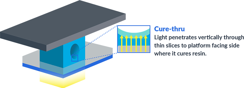
Optical overcure and cure-through
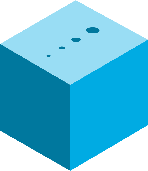
Resins used in photopolymer processes like LSPc are not completely opaque, so light will penetrate through thin areas of material triggering overcure and/or cure-through. These effects are not problematic in most cases unless the parts are quite small or you’re trying to achieve very tight tolerances with your design. By understanding these two occurrences, you can easily accommodate for them in your design and build set-up.
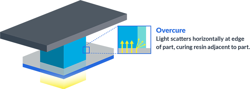
Overcure (XY plane)
Overcure occurs when light from the UV light engine scatters past the edge of the mask and cures the material near the mask boundary causing additional 0.01-0.05 mm of curing beyond the mask boundary. Scattering is primarily caused by dyes and fillers in the resin, so correction factors differ by material. Overcure increases with exposure time and typically exceeds 0.05 mm on the base layers.
Cure-through (Z axis)
Cure-through is an effect initiated by UV light from the light engine penetrating through the existing layer of material causing additional curing. This is necessary to achieve layer to layer adhesion. Cure-through results in overcuring of material in the Z axis. The depth of cure-through is material dependent with high resolution materials having cure through in the range of 0.02-0.05 mm and some transparent materials having cure-through as much as 1.0 mm.
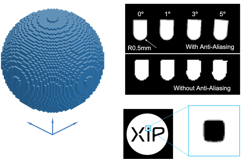
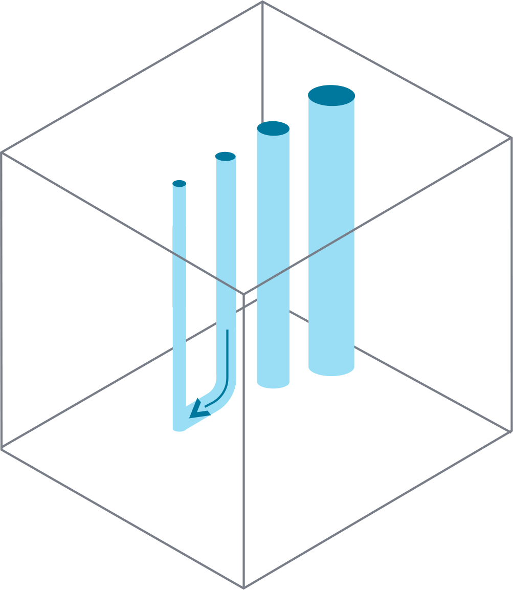
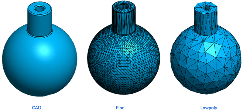
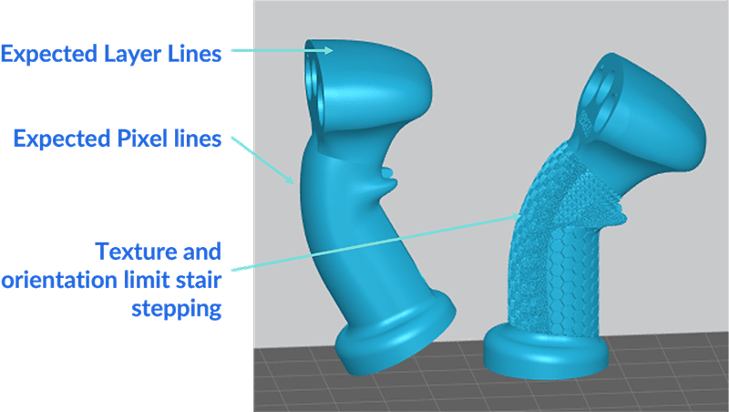
Voxelization
Printed models are expressed as voxels with
- XY resolution = pixel size of the mask
- Z resolution = layer height
- Anti-aliasing applied to XY edges by default
Design Advice
- Design with build orientation in mind
- Use surface textures and organic shapes
- Target feature size > 5 voxels.
Dealing with It
- Orient orthogonal to the cartesian Csys, or at angle greater than 10° to any axis
- Reduce layer height to minimize stair-stepping, or for higher resolution in Z
Design Guidelines
Much like injection molding or other 3D printing processes, it’s important to keep product manufacturability at the top of your mind. These design guidelines will help you produce the best possible parts and leverage the ultrafast capabilities of the XiP and NXE Series with LSPc® technology.
1. Wall thickness
Walls thinner than 0.8 mm may saturate through during washing, so limit wash times. Support contacts should be < 0.5 mm wall thickness when used.
Thicker walls may prevent complete post cure and could exotherm while printing affecting part quality. Thick parts or walls > 25 mm may be printed at slower speeds introduced to control temperature and shrinkage.
Possible |
|
| MIN wall freestanding | 0.5 mm |
| MIN wall with edge reinforcement | 0.3 mm |
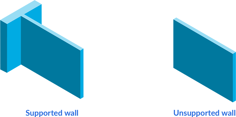
Ribs
In order to maintain form during post-cure, target a 25:1 aspect ratio for large surfaces. In other words, a 1 mm wall should have stiffening ribs spaced every 25 mm.Rib height increases the effective wall thickness, so use a 1 mm high rib for a 50 mm span and 3 mm rib for a 100 mm span.
Recommended |
|
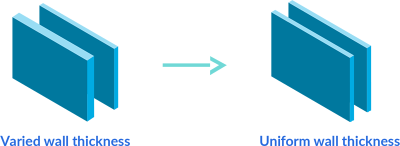
| Walls | 1-5 mm, uniform, 8:1 aspect ratio |
| Rib spacing | ~25:1 aspect ratio (i.e. for 1mm wall, a rib every 25 mm is recommended) |
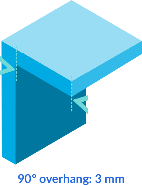
2. Overhangs and bridging
Horizontal overhang
A horizontal overhang is any part of the model that extends out parallel to the build platform. These features are common and printing them without supports is not recommended. Horizontal overhangs beyond 2 mm should be supported. If these overhands are not supported, they will likely incur deformation.
Recommended |
Possible |
|
| Horizontal Overhangs | <2 mm | Up to 4 mm |
| Horizontal Spans | <5 mm | <20 mm |
| Horizontal Spans | >30 deg | >5 deg |
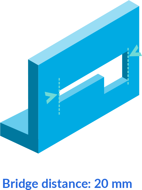
Bridging
Horizontal surfaces bridged between walls or supports may span twice the distance as overhangs. This applies also to support influence radius (use influence radius of 1.5 mm for horizontal surfaces at 0.1 mm). Spans as large as 20 mm are printable with a loss of some dimensional accuracy.
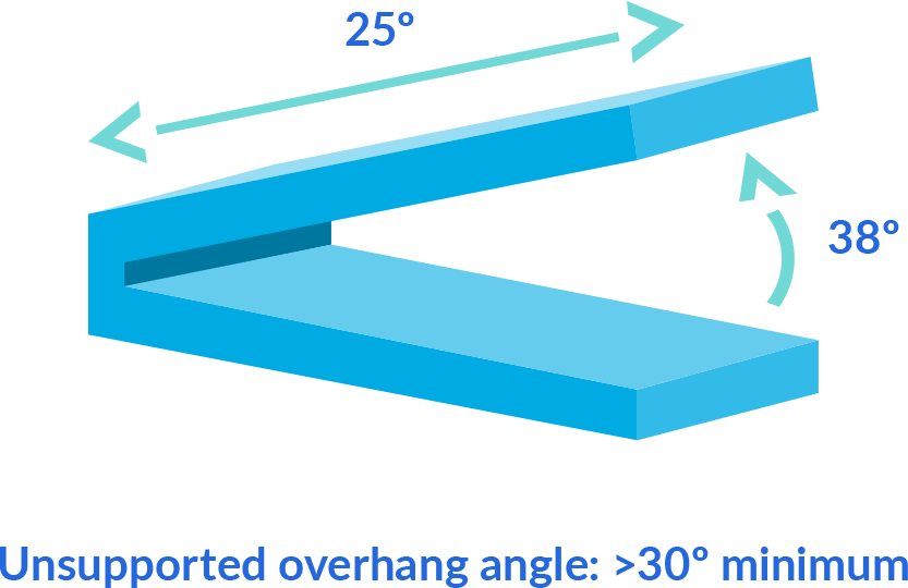
Angled overhang
An angled overhang is an overhang that extends out in any direction other than parallel to the build platform. These overhands require a 30° minimum angle in order to build self-supported. If the angle is below 30°, supports must be used to ensure the design prints as intended. Otherwise, these low degree angles risk delamination/peeling.
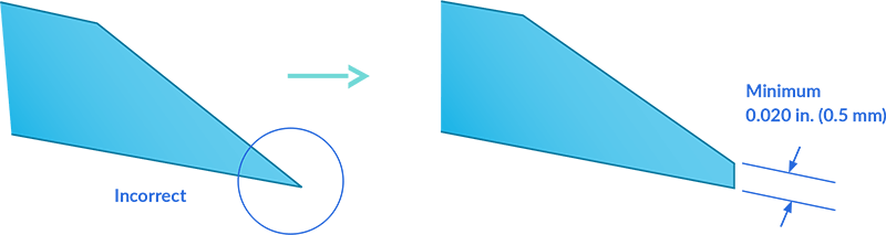
3. Feathered edges
A feathered edge should be blunted to 0.3mm or higher, or you risk damage and waviness during post-processing. Further blunting is required in the case of vibratory polishing.
Recommended |
Acceptable |
|
| Bluntness | >0.3 mm | >0.15 mm |
| Bluntness for Vibratory Polish Applications | >1.5 mm | >1.0 mm |
4. Holes
Minimum Hole Diameter
Holes smaller than 1.0 mm in diameter may close during printing due to cure-through. Larger holes may be required for clear resins. Smaller holes are possible when oriented vertically. Cleaning holes may be a challenge. Avoid blind holes and holes with large aspect ratios. Washing with a pressurized jet may be required to clean uncured resin out such holes.
Recommended |
Possible with
|
|
| Vertical holes size | >0.8 mm | >0.3 mm |
| Non-vertical hole size | >1 mm (opaque resin) >2 mm (clear resin) |
>0.6 mm |
| Blind hole depth | <3x diameter | <8x diameter |
| Through hole length | <8x diameter | <25x diameter |
Blind Holes
Blind hole depth is limited for holes below 3 mm diameter, where surface tension prevents resin from draining. Washing with a pressurized jet, such as with a syringe allows for deeper holes. Add vents to bottom of blind holes whenever possible.
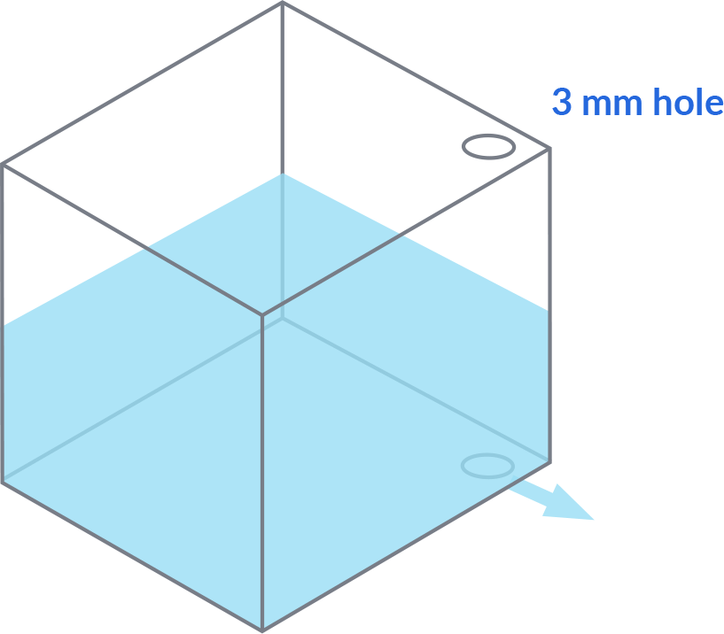
5. Hollow and Cupped Geometry
Enclosed Volumes
Drain holes are required in case of an enclosed volume, such as a hollowed part. The drain hole is used to allow resin to be flushed from enclosed cavities in your model. Without drain holes, uncured resin would remain trapped in the part and potentially result in part damage. Use at least two 3 mm diameter holes to allow cleaning the part, or at least 5 mm diameter if only one hole is possible. It is best to place holes near corners where resin and solvent would naturally flow.
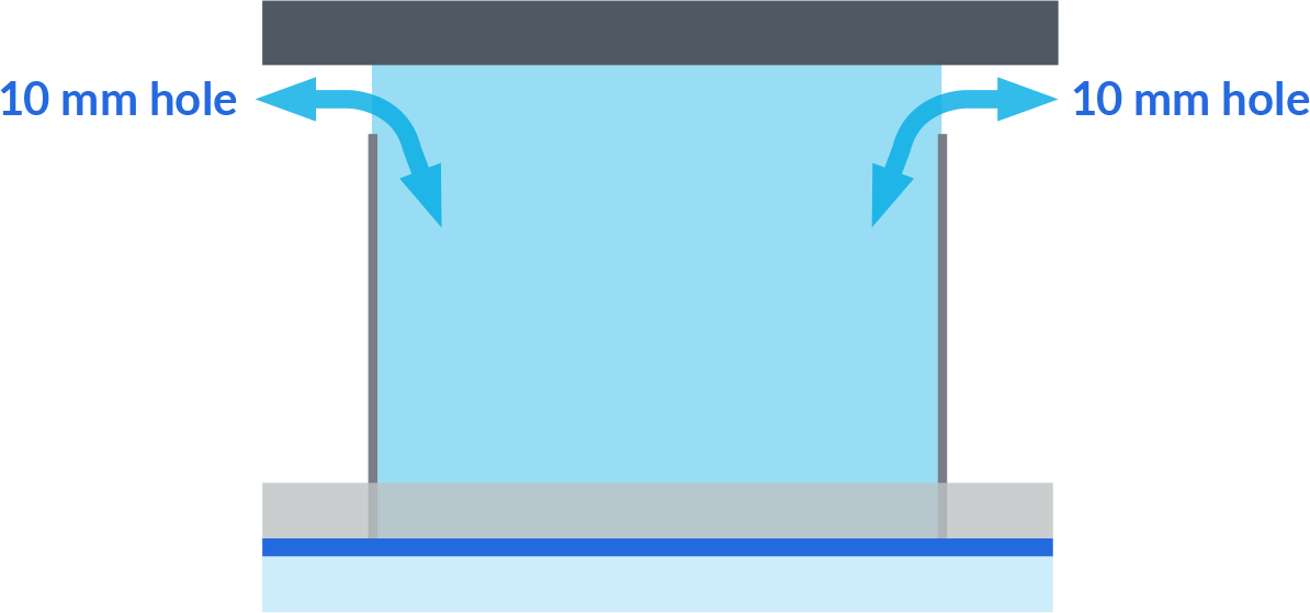
Venting and Cupping
If a cup-shaped feature is printing open to the vat, the resin will be pulled up by vacuum when the Z-axis lifts to separate, and the resin will pressurize when the axis returns to the platform. To avoid defects, place a vent hole at the base of the feature. NexaX allows adding tapered holes and matching plugs so the hole can be patched after printing. The hole should be sized appropriately for the size of the trapped volume – a diameter of 10% of the volume span is usually sufficient.
6. Threads, inserts, and fastening
Threads
Large threadforms designed to be molded from plastic, such as used for bottle caps are no problem for LSPc technology. The threads should be printed with axis approximately perpendicular to the platform to avoid defects from supports.
Machine threads designed for metal fastening may be functional as low as size M4 or US series No.8, however cure-through may affect the threadform and cause friction. Chase machine threadforms with a tap or die when possible after curing. These threads are not ideal for repeated fastening.
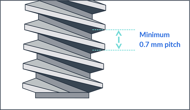
Recommended |
Possible |
|
| Thread Size | >M10x1.5 >3/8-16 UN |
>M4x0.7 >#8-32 UN |
Fastening with Metal Bolts and Screws
When fastening with machine bolts and screws, it is recommended to use a metallic insert such as a hex nut, heat-set insert, or stand-off to avoid over stressing the plastic. Heatset inserts are best installed before post curing. If using a threadforming screw designed to screw into a thermoplastic material, select a tough material like xABS or xPP or the screw may crack the boss.
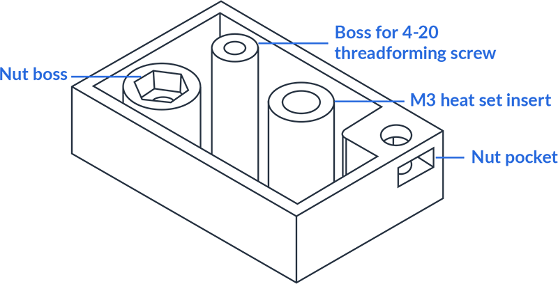
Snaps
Snap fit connections should be designed for the material used. The snap length, thickness and interference should keep elongation below 50% the material’s limit. At about 85% elongation, xPP material class works well for snap fits designed for molded polyamid.
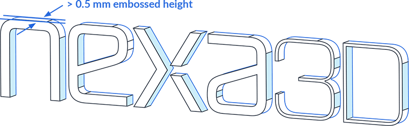
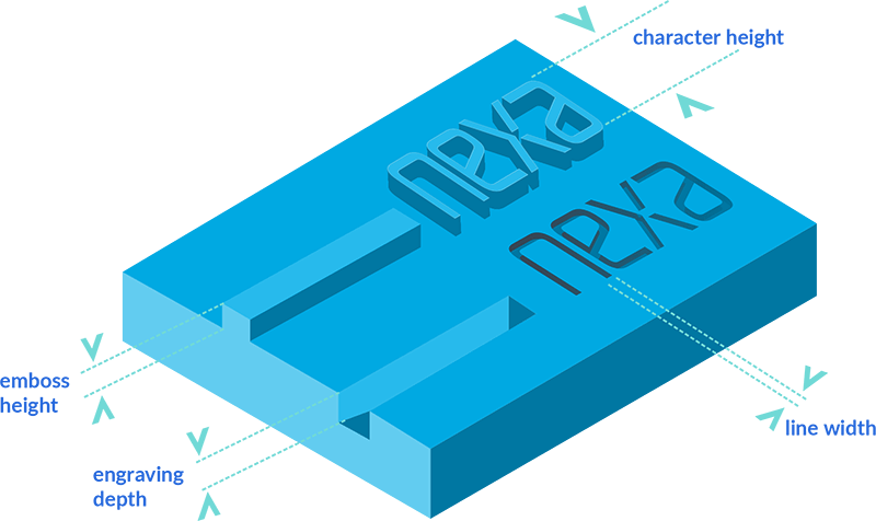
7. Integrating text, engraving, and embossing
Text and other surface features may be embossed on or engraved into the primary part surface. Typical text height for most sans-serif fonts should be above 4 mm and use an emboss height or engrave depth equal to line width of the characters for best readability.
Avoid calligraphic or serif fonts for small text since they often include elements with narrow line width.
If using engraved text on the down-skin surface (facing the build plate), stay within the recommended size range, and use rounded or beveled edges. Islands (like the center of letter O) require support or should be filled in.
Possible |
Recommended |
|
| Character Height | >2.5 mm | >4 mm |
| Emboss Height / Engrave Depth | >0.25 mm | >0.5mm, or equal to line width |
| Line Width | >0.25 mm | >0.4 mm |
File and Print Preparation
Now that you have your design completed, it’s important to prepare your file and build set up to take advantage of the best possible production speeds and part quality.
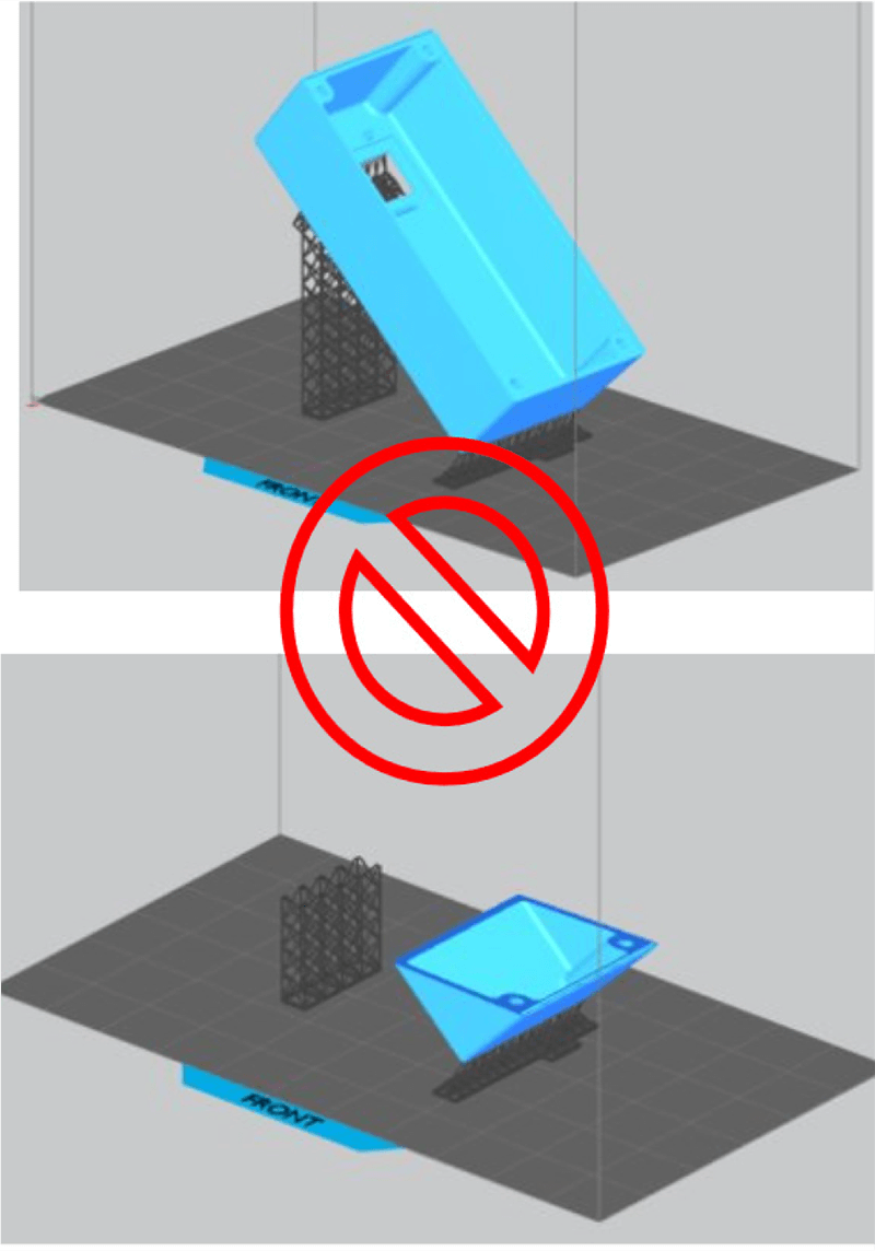
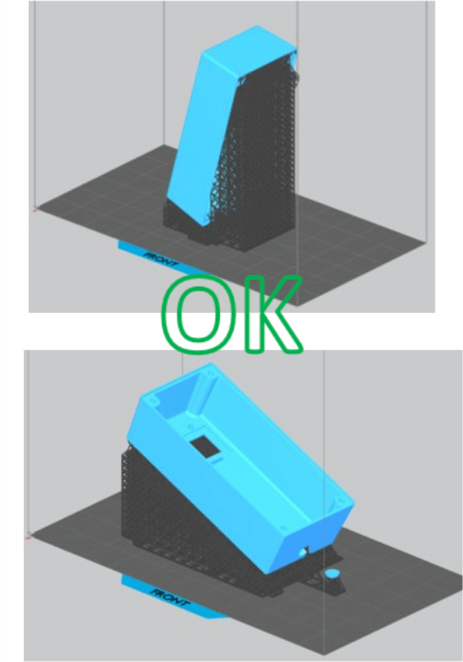
1. Orientation and supports
Ensure there are supports at all local minimum points, including text or texture features greater in size than layer height.
When supporting large shallow-angle or horizontal surfaces, use a higher support density, smaller cell size, and smaller influence regions.
When supporting surfaces in the range of 30-60°, the default settings can be used. Generally the density can be decreased (influence radius increased) as the angle of the supported surface increases.
Place supports on surfaces from which they can be easily removed and sanded.
Avoid supports on locating surfaces or inspection datums.
NexaX gives you the freedom to fully configure support parameters and edit individual contact point locations and sizes. When unsure about the best support strategy for your part, you can view multiple configurations within a single build to test them out.
2. File Preparation
Coarser models, while suitable for some other processes, may exhibit faceting when printed on LSPc printers. Meshes must be closed volumes (manifold) and joined (boolean addition) to process reliably, however the software is robust to many mesh quality issues.
NexaX 2.0 file preparation software provides insight on the printing time and material usage. You can also use the build slider to visualize how the parts will grow on the platform.
Recommended |
|
| Deviation Tolerance | 0.05 mm |
| Angle Tolerance | 5 degrees |
3. Orientation and support generation
4. Mating orientation, part clearance, and uniformity in slices
Mating Parts
If you are printing mating parts, it’s best to match orientations to obtain the best fit. Try to put mating surfaces on the upskin (away from build plate) as these features are the most precise.

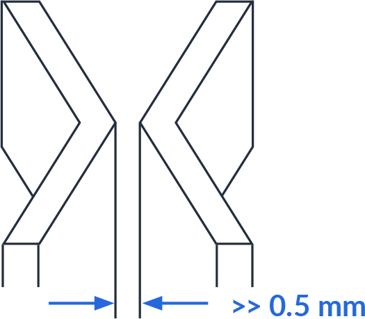
Clearance
Clearance, also known as spacing, is the amount of distance between two components of an assembly or two parts on the build platform.
It’s important to ensure your parts and assemblies are appropriately spaced to provide the necessary clearance and avoid any issues while printingand to ensure proper functionality of the final part.
The minimum spacing recommended for LSPc technology
is 0.5 mm for both assembly components as well as separate parts on the build.
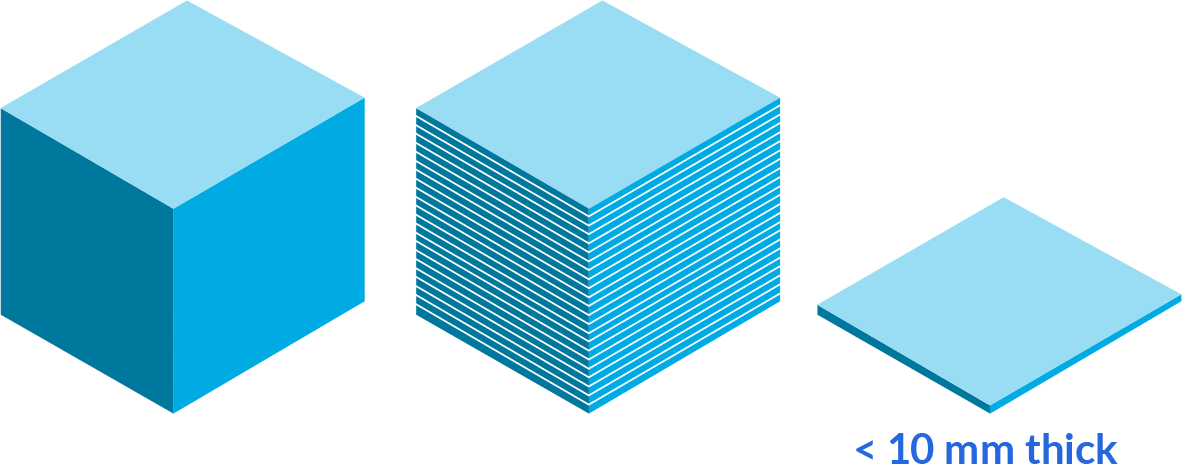
Uniformity of Slices
Design and orient parts so that the sliced sections will have less than 10 mm thickness, that means walls of 5 mm should be oriented > 30 deg. Abrupt changes in cross sections will have high differential shrink causing surface bands and may cause warping.
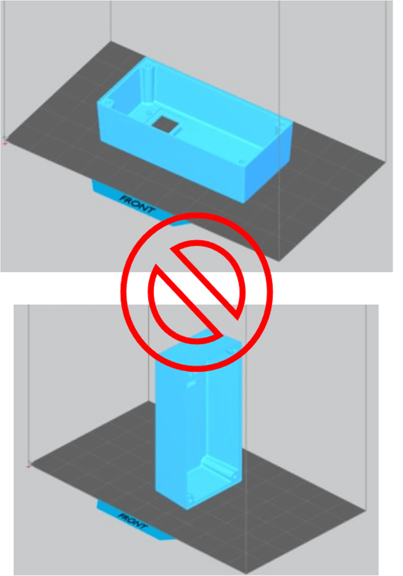
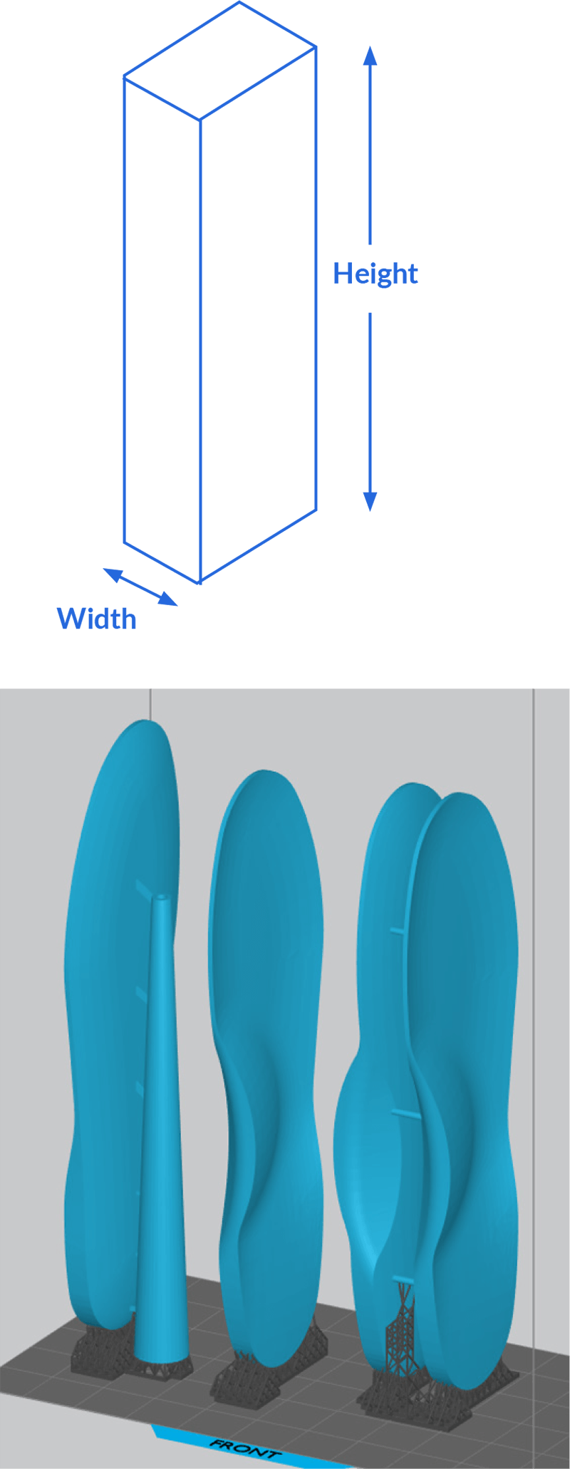
5. Orientation—managing high aspect ratios
When the design or your supported part is slender (has a high ratio of height to build-plate contact-width), is it is likely to sway during printing. You might find walls thickening as you move away from the build plate, or supports breaking, causing layer lines. Choose appropriate part orientation and support strategy to accommodate these features.
The best option is to reorient your part to limit the height of the build. If the feature in question cannot be reoriented, then design the feature perpendicular to the build platform to prevent drag forces from deflecting the feature.
Elastic materials are most sensitive to high aspect ratios. Target a ratio less than 3:1 when working with these materials. For exceptional parts, reduce the aspect ratio by printing parts back-to-back or attached to a support mast.
Recommended Max Slenderness |
|
| High Strength Materials | 12:1 |
| Impact Resistant Material | 8:1 |
| Photo Elastomers | 3:1 |
6. Fine features and stair-stepping
When fine features are present it’s critical to apply the correct orientation for feature resolution. Print thin walls, critical diameters, and threads perpendicular to the build plate so supports are not required. Shallow angles greater than 5° may cause a stair-stepping effect at near-horizontal cross-sections.
Recommended |
Acceptable |
|
| Orientation | 0°, 90°, 15°-75° | 1°-14°, 76°-89° |
Quick Reference Guide
We hope you’re inspired to lead a revolution in your industry, and we’ve sparked some ideas of how the world could be. Armed with a better understanding of Nexa3D’s manufacturing and materials ecosystem, you’re ready for the next step.
Design and Print Prep Quick Reference for LSPc 3D Printing
Just like molding, parts designed for the process come out repeatably. Staying within the recommended design guidance minimizes post processing effort and maximizes accuracy. Parts at the design limits may require certain orientation, size, material, build parameters, or post-processing techniques.
Feature |
Recommended |
Possible |
|
|
All Materials |
Strong (xCE, xGPP, xPRO, x45, xPEEK) |
Impact Resistant (xABS, xPP) |
Elastomeric (xFLEX) |
|
Wall Thickness |
1-5 mm | 0.3-25 mm | 0.6-25 mm | 0.5-50 mm |
Wall span between ribs |
<25x thickness | <50x thickness | <35x thickness | <12x thickness |
Minimum feature size |
>0.5mm projection >1mm hole |
>0.3mm projection >0.3mm hole |
>0.6 mm projection >0.5 mm hole |
>0.8 mm projection > 0.6 mm hole |
Hole depth |
<3x Diameter (blind) <8x Diameter (thru) |
<10x Diameter (blind) <25x Diameter (thru) |
<8x Diameter (blind) <25x Diameter (thru) |
<4x Diameter (blind) <12x Diameter (thru) |
Text, embossed or engraved |
Depth: 0.4-0.8mm (=line width) Character height: >4mm |
0.2-1.5mm depth 2.5mm height |
0.2-1.5mm depth 2.5mm text height |
0.2-1.5mm depth 2.5mm text height |
Unsupported angle |
>30º | >5º | >10º | >40º |
Unsupported overhang |
<2mm | <4mm | <3mm | <2mm |
Unsupported span |
<5mm | <20mm | <15mm | <8mm |