
- How to Design 3D Printed Tooling - August 15, 2023
From manufacturing to healthcare, consumer goods to automotive parts, 3D printing has carved for itself a sizable niche as a solution for tooling. The term, “tooling” refers to the molds, patterns, and tools used in the manufacturing and assembly processes.
In this post, the key focus will be on 3D-printed tools for injection molding, an application that dramatically expands the applicability of 3D-printing and is emerging as a high-impact bridge between the traditionally separate domains of additive manufacturing and injection molding.
The key reason anybody would want to start 3D printed injection molding tools is that injection molding offers access to a much wider range of materials than pure-play additive manufacturing. Recent innovations in the field have brought high-performance materials such as glass-filled and carbon-filled PEEK, and also silicones, metals and ceramics, into the portfolio of 3D-printed tooling. And depending on the choice of technology, increased design freedom, lower costs, shorter lead-times, biocompatibility and scalability may also be among the key benefits offered by 3D-printed injection mold tooling.
If you wish to 3D-print your injection molding tool, you must first create a 3D model of the part you wish to mold and determine what material(s) you want to inject. The design of the part, and the pressure and temperature needed for the injection, will guide you in the choice of technology and the design of the 3D-printed mold. If your part features undercuts, inserts, over-molded sections and other complications, you should look towards 3D-printed tooling technologies offering the necessary design freedom. And if your part is to be made in a high-performance material injected at high temperatures and pressures you will want a solution that has demonstrated compatibility with the material you want to use.
Once you have completed the design of your part, your next step is to translate the part design into a tool design. Depending on your choice of 3D-printed tooling technology, you may have to decide how to split your tool to get your part out. For complex parts, the design of a split tool may be a multi-week exercise involving multiple iterations. Alternatively, you may opt for sacrificial / soluble 3D-printed tooling or tool elements to postpone or eliminate mold design complications and enable new levels of design freedom.
Once tool design is completed, you will have to manufacture the actual tool. Again, your choice of 3D-printed tooling technology will determine what costs, time and post-processing work are involved in the manufacturing. At one extreme are the 3D-printed soluble tools used to break time and design constraints in processes like Freeform Injection Molding, which require only a simple cleaning and post-curing before they can be applied. At the other extreme are found the complex metal inserts with conformal cooling that are used to enhance the functionality and performance high-volume production tools, and which may require the use of sophisticated machining, polishing and hardening processes to deliver the millions of shots they are designed for.
In summary, 3D-printed injection mold tooling is a rapidly evolving and highly diverse field that is already adding substantial value at every step of a product lifecycle. At Nexa3D, we are dedicated to provide more companies with easy access to the benefits of 3D-printed tooling, with our ultrafast LSPc platform as the cornerstone. Have a look at the experience won by companies such as Wilson Sporting Goods, PepsiCo or Alpine Advanced Materials, or read on to learn more about how to design tools for Freeform Injection Molding.
Design Considerations
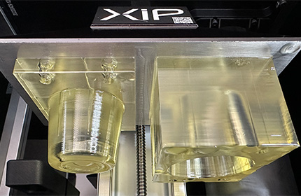
Freeform Injection Molding (FIM) is based on the happy marriage of the LSPc technology found in the XiP, XiP Pro and NXE 400Pro and our novel xMOLD material, which combines best-in-class thermal and mechanical stability with solubility. FIM provides mold designers with new levels of design freedom, and access to the entire range of injection-moldable materials including silicones, high-performance thermoplastics, metals and ceramics. Below, we have summarized some of the key design considerations that will help you avoid common pitfalls in the design of tools that are both printable and suitable for injection molding.
Listed below are some tips on optimizing the CAD model’s geometry to ensure printability:
- Optimizing Wall Thickness – The geometry of your model’s walls determines whether they can be printed with or without supporting features. Models with thicker walls (over 1 mm thickness) are most often printable as designed and may not require additional support. Also, it’s a good idea to design supported walls that are connected to other walls on one or more sides because the connections act as in-built support features. Conversely, where unsupported walls are necessary, you’ll need to make special design considerations. If possible, thicken the wall beyond that 1 mm threshold.
- Optimize Overhanging Structures – Overhangs refer to the parts of your model that stick out or hang parallel to horizontal surfaces and the printer’s build platform. The length of this overhang is a critical consideration and you’re usually best off limiting it to 2.5 mm. Portions that overhang by too much will deform while they’re being printed.
- Optimize Modelled Details – Most surface details on a 3D printed model fall into two categories: embossed and engraved details. Embossed details are those features that are raised above the surface of your model. You should generally not design embossed print details with a thickness of less than 0.02 mm. More subtle detailing may not translate properly into the final print. Engraved details that are imprinted onto the surface of the model have a similar limitation. The imprinted or recessed features on your model should not have a thickness and height of less than 0.02 mm.
- Designing Optimized Holes – Holes are critical features in many tooling models. Your straight holes must not have a diameter less than 0.7 mm — any smaller and they may get inadvertently blocked during the 3D printing process. For models with curved canals, ensure that the diameter is not less than 1 mm.
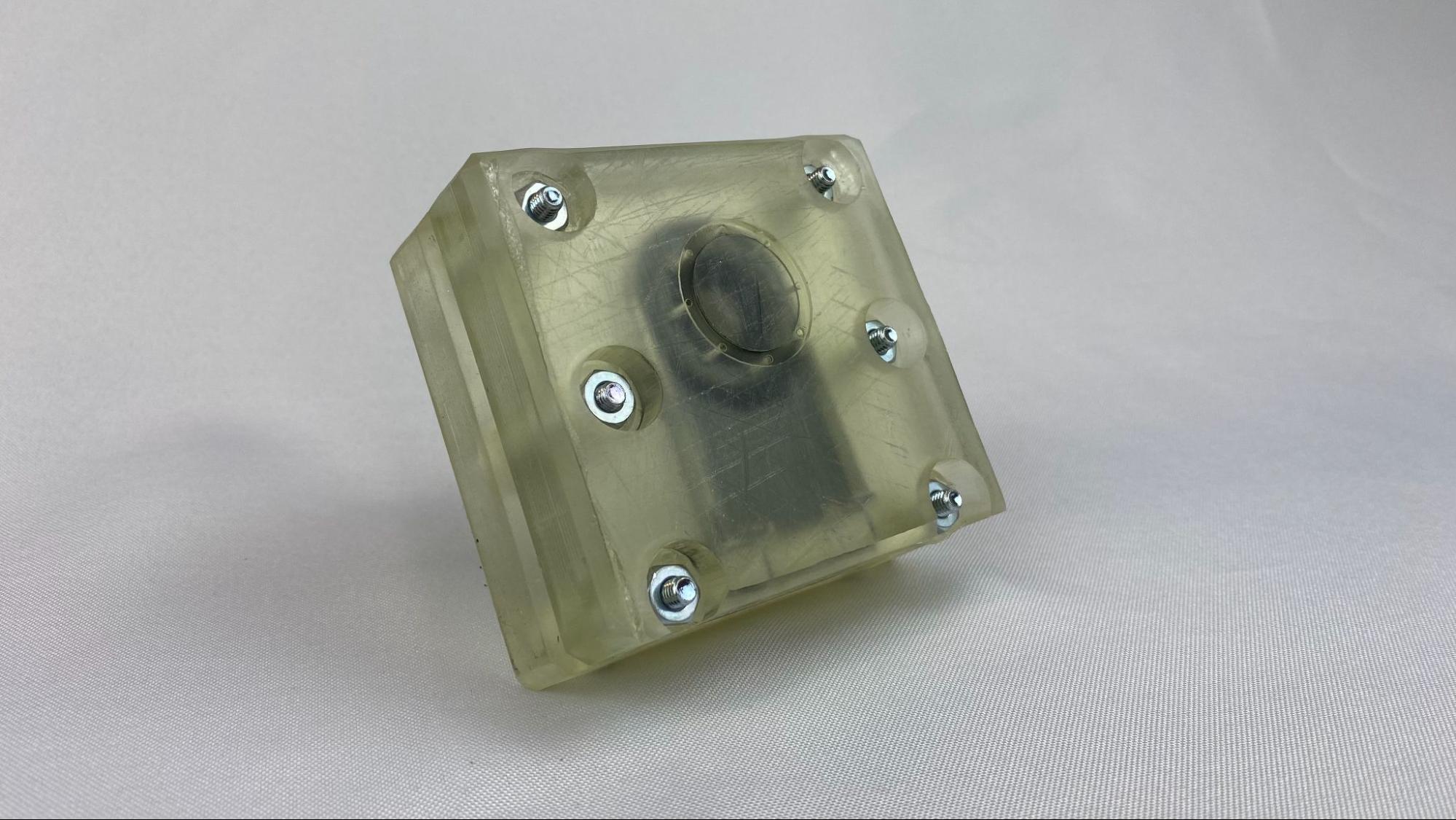
- Split Molds to Optimize Printability – While tools printed with xMOLD resin are soluble, and it is often easiest to design single-cavity molds, the presence of overhangs and other hard-to-print features may require that a mold be split. Large 3D-printed tooling may also require that multiple mold elements are printed separately and then joined. In those cases, we recommend including holes for bolts and pins to facilitate mold alignment and assembly.
- Consider Clean-ability – especially when designing fully soluble closed-cavity molds. You will want to ensure that your cleaning solvent can reach – and flow through – every corner of your mold, as any uncured resin left in the mold after cleaning will negatively influence mold precision. Incidentally, by ensuring good cleanability you are also taking important steps to ensure that your mold can be filled appropriately during the injection molding process.
- Check Build Orientation – Some printing difficulties that arise from overhangs, wires, and unsupported walls can be eliminated simply by orienting the print differently on the support base. You want both the base and gravity to work in your favor while the print is underway. You’ll also want to orient your item such that detailed surfaces are not printed directly onto the build platform because it can deform the detailing.
- Leverage 3D Printing Software Modes – Modern CAD tools contain design modes and features dedicated to 3D printing. Use these features to help optimize part orientations, holes, details, overhangs, and supporting structures. When attached to best-in-class 3D printers like Nexa3D printers, the 3D software will add further guidance on slicing modeled files to ensure a successful print. 3D printing software also provides additional orientation support for STL files or models developed through molding or 3D scanning processes.
Design Tips to Eliminate Common 3D Printed Tooling Problems
Listed below are some suggestions optimizing the CAD model’s geometry to ensure moldability:
- Consider the placement of gates and vents to promote an optimal flow of materials – gate and vent placement are critical factors to consider to ensure that the feedstock material reaches all areas of the mold before hardening to eliminate warping and voids. Gate placement should follow the guidelines for conventional tool design, and we recommend using mold flow analyses where possible to ensure proper filling. Vents are preferably placed opposite the gate, and at, or close to points at the end of the fill. The vents – depending on their design – may also be used to capture any potential cold slug, and they provide an easy way for the operator to check if a mold has been properly filled before demolding is initiated.
- Consider the thickness of walls and protruding structures – the xMOLD material is sturdy, but it will deform if excessive pressure is applied. As a rule of thumb, aspect ratios larger than 2:1 should be avoided, which means that e.g. a freestanding structure can be no more than 2 mm long, if it is 1 mm thick. Also consider the flow-path of the injected material, to possibly avoid directing a hot stream of material directly across a freestanding structure.
- 3. Consider using metal inserts (e.g. pins) to support or enable through-holes and other mold geometries – The inclusion of metal elements (e.g. off-the-shelf steel pins or rods) may provide support to free-standing structures, or facilitate the provision of through-holes and other part features.
The above are some of the key principles to observe when designing a 3D-printed injection molding tool that is both printable and suitable for injection molding. Learn more about the Freeform Injection Molding process by downloading the free Design Guide, or get in touch with one of our 3D-printed injection mold tooling experts if you want specific guidance on how to turn your Nexa3D LSPc printer into a tool-making workhorse.
More on Freeform Injection Molding
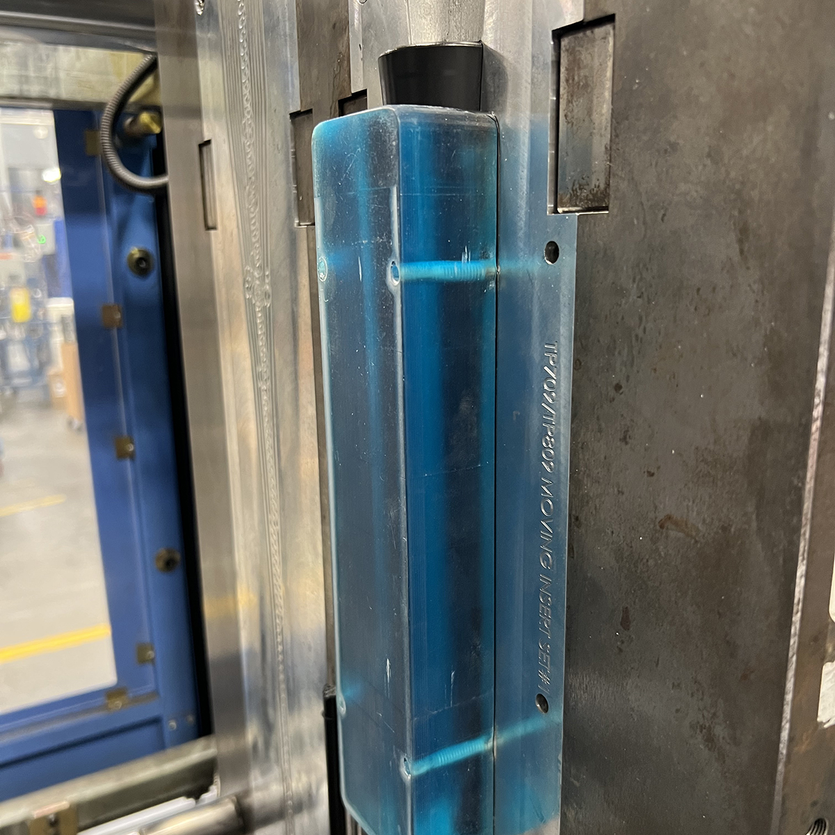
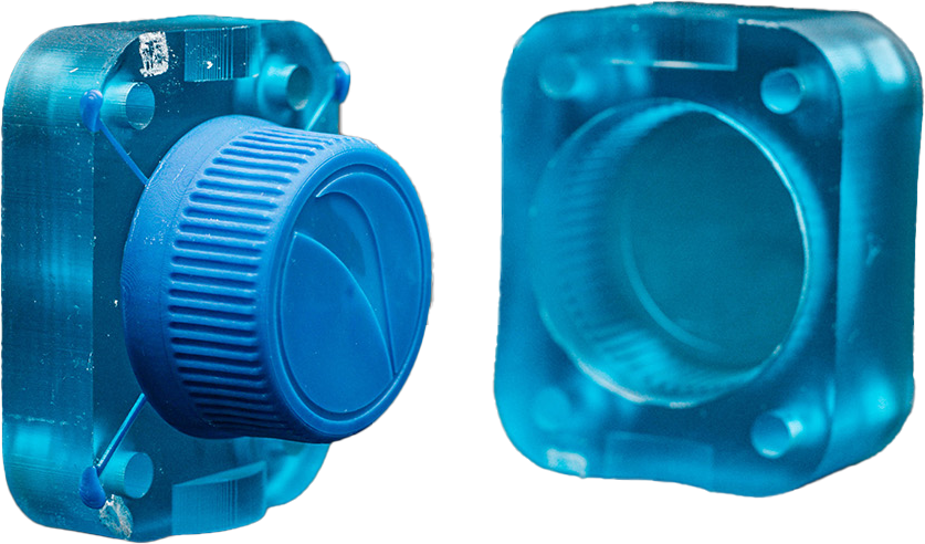
Freeform Injection Molding is an innovative hybrid manufacturing approach to injection molding. It combines the design freedom of resin 3D printing with the performance of injection molded materials. The patented process combines ultrafast Nexa3D printers and xMOLD resin to print injection molding tools that are compatible with thousands of off-the-shelf injection molding materials, including reinforced high-performance feedstocks. The ability to design, iterate, and validate tools using final grade production materials in hours versus weeks is invaluable in the new product development process.
The xMOLD tools are fully soluble, enabling true design freedom and eliminating the need for time consuming design and gating considerations typically associated with conventional tooling practices. Simply design and print your tool, inject with injection molding feedstock, and then dissolve away the tool to reveal the complex part underneath.
Download the Design Guide for 3D Printed Tooling
Comprehensive set of design guidelines for Freeform Injection Molding
Succeed With 3D Printed Tooling
Designing 3D printable models is only one step in the 3D printing process. You must also consider which materials to use and what 3D printer capabilities will produce the most precise end-use tools. You can find guides on choosing the right materials and 3D printers here.
Nexa3D is the leading provider of high-quality 3D printers and 3D printing materials. Talk to a Nexa3D expert today to learn more.