
- Best 3D Printers (Industrial, Desktop, & More) [2024 Guide] - July 20, 2024
- Best Filament 3D Printers [2024] - June 25, 2024
- 9 Best FDM 3D Printers (Plus FDM 3D Printing Guide) [2024] - June 24, 2024
Metal Injection Molding (MIM) is a metal part production technique that seamlessly incorporates the precision of plastic injection molding with the strength and durability of metal manufacturing, resulting in the precise production of complex metal parts. This process revolutionizes traditional metal production processes, transforming how we create custom complex metal components.
This guide dives into the intricacies of MIM, exploring its principles, advantages, applications, leading alternatives, and the best metal 3D printers to elevate metal production processes.
What is Metal Injection Molding in 3D Printing?
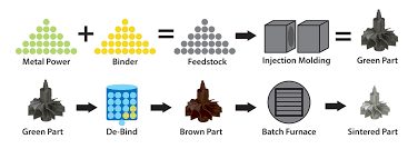
Metal injection molding is a manufacturing technique that fuses powder metallurgy with plastic injection molding. In this intricate process, finely powdered metal is mixed with a binder material to create a feedstock, which is then injected into a mold cavity. After molding, the resulting part undergoes a debinding process to remove the binder and is subsequently sintered at high temperatures to achieve its final metal state.
MIM combines the design flexibility of plastic injection molding with the strength and durability of metal materials, making it a versatile method for producing complex and precise metal parts. It plastifies powdered raw materials with the help of thermoplastic additives, making it easier to create solid metal structures with extreme accuracy from a variety of materials such as metal alloys.
Metal Injection Molding vs Die Casting
MIM is an intricate method that merges plastic injection molding as we know it with metal production. It uses powder metallurgy to create high-strength metal parts and components.
On the other hand, die casting doesn’t utilize powdered metal. Instead, it involves the high-pressure injection of molten metal into a die created in the shape of the object to be formed. After the molten metal cools and takes shape, the resulting structure is a durable metal part made precisely in the shape intended by the hollow die.
Die casting is typically used in the manufacturing of non-ferrous metal parts using metals and alloys such as aluminum, brass, tin, zinc, copper, magnesium, and lead. Due to its versatility and design flexibility, die casting is employed to manufacture parts across countless industries such as healthcare, automobile, military, and more.
Metal Injection Molding Process
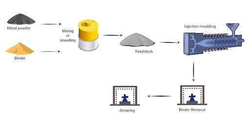
1. Preparing MIM Materials (Feedstock):
The process begins with creating a feedstock consisting of two major ingredients: metal powders and a thermoplastic binder.
The metal powder forms the foundation of the process as its properties determine the properties of the metal structure created. The thermoplastic binder is simply an additive or intermediate processing aid that helps shape the mixture and is removed from the products after injection molding.
The metal powder and thermoplastic binder are mixed and worked into the plasticized binder at extremely high heat using a kneader or shear roll extruder.
Kneaders and extruders are devices used to shred the feedstock powder into fine particles. This ensures the metal powder and thermoplastic binder are broken down into consistent particles, thereby minimizing distortion during the future sintering processes.
The resulting mixture after the metal powder is thoroughly combined with the thermoplastic binder is a granulated powder known as the feedstock.
2. Injection
The prepared feedstock is injected into a mold cavity, typically under high pressure, to shape it into the desired ‘green’ part or component. The green part is the resulting part that undergoes further processing to become the final part.
The injection step is similar to plastic injection molding, the only difference being the metal-infused material. As a result, the injection molding process of MIM can produce intricate designs similar to the injection molding process of plastics.
3. Binder Remover
The part created after molding contains both the metal powder and the binder material. The next stage involves removing the majority of the binder from the molded part.
Binder removal is typically performed through a debinding process, which can include solvent extraction or thermal methods.
In solvent extraction, a major portion of binder particles is removed using solvents such as acetone, trichloroethane, or heptane to degrade the soluble binder. On the other hand, thermal extraction uses heat to separate the metal powder from binder particles by completely evaporating the binder.
Regardless of the method used, the goal is to eliminate binder particles in the “green” part, leaving behind what is known as the ‘brown part,’ a part with even fewer binder particles in it.
While the binder remover process doesn’t completely eliminate all the binder in the part created, the pore network allows the residual binder to evaporate quickly during the initial sintering phase.
As the binder particles evaporate, they leave behind pores which are eliminated as the metal particles fuse together during sintering. As the metal particles begin to bind together, they form what is known as “sinter necks.” Compacting metal particles gives the part enough stability to undergo the final sintering process.
4. Sintering & Any Secondary Finishing
Sintering in MIM involves heating the metal part at a temperature just before its melting point, making the part hot enough without undergoing liquefaction. It is typically performed to bond the metal particles, closing the gaps left behind during the debinding process.
After the binder removal process, the “brown” part is subjected to high-temperature sintering in a controlled atmosphere such as a furnace. The exact temperature and sintering time usually depend greatly on the material and design of the part.
During sintering, the metal particles fuse, and the component shrinks to its final dimensions while achieving full metal density.
One of the many advantages of MIM is it requires less post-processing compared to other metal manufacturing processes like traditional metal casting.
After sintering, the final parts may undergo additional secondary finishing processes to meet specific design requirements. These secondary processes include:
- Machining
- Surface treatment
- Heat treatment
- Surface carburization
- Joining
- Coining
MIM Advantages
Reduced Material Waste
MIM generates less material waste compared to traditional manufacturing methods. It optimizes material use by shaping metal powders into near-net-shaped parts, minimizing material scrap. As a result of this minimal waste production, MIM is considered a green technology, especially when combined with printers that facilitate less waste production.
Complex Geometries
MIM excels in producing durable metal parts with intricate and complex geometries that may be challenging or expensive to achieve through other manufacturing methods. This makes it ideal for production processes requiring precise and intricate components.
The ability to create elaborately shaped metal structures makes MIM a strong candidate for application in industries such as aerospace, automobile, and healthcare industries. With access to a range of material choices that vary from stainless steel, titanium, and low-alloy steels, MIM offers the flexibility to choose the best material for the specific geometry and industrial application.
Cost Effective
MIM is often a cost-effective option for small to medium-sized parts production. It permits the small-scale production of custom metal parts while minimizing material waste and ensuring the need for minimal to no secondary operations, such as machining, welding, or assembly.
MIM Limitations
Sintering Shrinkage
During the sintering process of MIM, metal parts experience a reduction in size due to the elimination of binder particles. While this shrinkage increases the density of the metal part being produced, it also significantly reduces the size of the part.
This size reduction makes it challenging to achieve precise dimensional accuracy as manufacturers need to make additional dimension allowances to account for the shrinkage in their designs, so proper design expertise from someone with expertise in this area is crucial.
Limited to Smaller Parts
MIM is typically recommended and best suited for small to medium-sized parts. As part size increases, the challenges associated with sintering, shrinkage, and size distortion become more significant, making the process less suitable for large components.
Metal Injection Molding 3D Printing Alternatives
Although Metal Injection Molding (MIM) is a potent manufacturing process for metal components, several alternative 3D printing technologies offer distinct advantages in certain applications.
Some 3D printing alternatives for MIM include:
ColdMetalFusion
ColdMetalFusion (CMF) is an established process that is similar to MIM but with the added design freedom and fast production typically associated with 3D printing. It uses patented metal powder feedstock from Headmade® Materials, where each metal particle is coated with a thin layer of polymer.
This coating is crucial for bonding the particles together during sintering. The sintering is conducted at low temperatures in Nexa3D’s quick-cycle QLS printers, which use SLS 3D printing technology. After printing, the components undergo a standardized debinding and sintering process. This step effectively burns out and removes the polymer, yielding fully metallic parts.
ColdMetalFusion is compatible with all QLS series SLS printers. CMF merges efficient laser sintering with traditional powder metallurgy methods. The result is the production of metal components that exhibit superior performance, consistent repeatability, and high precision.
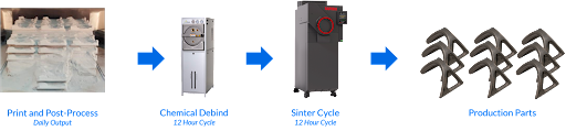
ColdMetalFusion 3D Printing Process
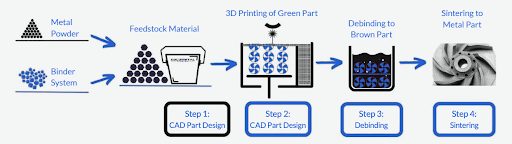
- Create a computer-aided design (CAD) file that acts as a model and map for the part to be created
- The CAD file is scaled up to account for expected shrink and is uploaded to a 3D printer such as Nexa3D QLS 3D printers
- The part is formed layer by layer by melting the feedstock to get a green part. The process takes place below 70° C, usually at 50° C, which minimizes heating and cooling time significantly
- The cleaned green parts are then debound using a solvent. Within the debinding step, one part of the binder system is detached from the green part at around 30 – 40° Celsius to get a brown part that still has high part strength. This is a cost-effective and ecologically conscious process used for many years in powder metallurgy
- The final process involves heating the brown parts in a furnace, where atomic diffusion fuses metal particles into dense parts and eliminates polymer binder residue; this technique also enhances safety by incorporating metal powder into a binder-matrix, thus reducing fire risks and simplifying material handling
ColdMetalFusion Pros
- An excellent material selection that varies from fan-favorite stainless steel to oft sought-after titanium
- Eliminate time-consuming and costly post-processing such as support removal, heat treatment, and stress relief
- High-resolution printing with lower production costs up to 90%
- Green technology that is sustainable and eco-friendly with the right printers such as Nexa QLS printers
- Facilitates design freedom that is not impacted by the constraints of traditional manufacturing or the limitations of direct metal laser melting processes
- Adopted across various industries such as aerospace, automobile, and healthcare
- Enables the creation of intricate metal parts with complex geometries
ColdMetalFusion Limitations
ColdMetalFusion is an advanced process that requires knowledge of the printing and production process and professional experience. As such, it is not the best metal processing method for hobbyists and small-scale businesses.
Best 3D Printers for ColdMetalFusion
Learn more about CMF in the Ultimate Production Guide to Metal 3D Printing
Freeform Injection Molding with xMOLD
The patented Freeform Injection Molding (FIM) process uses ultrafast Nexa3D printers and xMOLD resin to print injection molding tools used in metal production. This technological solution introduces design freedom and functional realism to the production of intricate and unconventional parts.
Freeform injection molding combines the speed and throughput of Nexa3D’s LSPc printers with the flexibility of xMOLD resin to revolutionize the tool-making process. It eliminates the need for elaborate traditional processes of creating tools, thereby shortening production time and helping manufacturers accelerate their time-to-market.
The technology’s ability to design, iterate, and validate using final grade production materials in hours versus weeks is invaluable in any product development process.
More importantly, the FIM process produces fully soluble tools. This makes it possible to quickly design and print tools for highly complex parts, inject the tools with injection molding feedstock, and then dissolve away the tool to reveal the complex shape underneath.
Freeform Injection Molding 3D Printing Process
- Design the CAD file of the part to be molded
- Convert the design to mold
- 3D print and post-process the mold.
Freeform Injection Molding Pros
- Cut tooling costs by 96%
- Iterate more frequently and quickly
- Choose from hundreds of injectable feedstocks
- Create more precise tools
Freeform Injection Molding Limitations
Mastery of this technology may require a learning curve for operators and designers due to its complexity.
Best 3D Printers for Freeform Injection Molding with xMOLD
The Bottom Line on Metal Injection Molding
Metal Injection Molding is used across various industries such as aerospace and the automobile industry. While it remains a robust and reliable method for many, MIM is bound by several limitations, like high material costs and an inability to be used for the production of large parts.
If you are looking for alternatives not bound by these limitations, then you should take a look at ColdMetalFusion and Freeform Injection Molding with xMOLD.
ColdMetalFusion and Freeform Injection Molding used with Nexa3D provides complete design freedom, functional realism, extensive material options, and extensive material options and final physical characteristics, which enables advanced R&D capabilities without the traditional constraints.
Are you ready to experience this innovation?
Learn more about ColdMetalFusion with Nexa3D and Freeform Injection Molding with xMold.
Access Ultimate Production Guide to Metal 3D Printing for Free